Arbejdstilsynet, The Danish Working Environment Authority (WEA) guideline 65.2.2 on Health and safety aspects regarding offshore well operations
August 2018
This guideline explains how offshore well operations should be designed and planned, constructed, maintained and performed throughout the life of the well until it is permanently plugged and abandoned.
The set of regulations on health and safety aspects of offshore well operations is one of the outcomes of the EU directive (2013/30EU) on safety of offshore oil and gas operations.
This guideline therefore explains how offshore well operations should be designed and planned, constructed, maintained and performed throughout the life of the well until it is permanently plugged and abandoned. This shall be done through reducing the risks of accidental releases of substances and materials that can lead to a major accident.
The guideline is intended for operators and rig owners involved in offshore well operations in the Danish part of the North Sea. The guideline is also intended for the safety representatives and employees as they must contribute to reducing the risks in accordance with the ALARP principle. Furthermore, the guideline is intended for drilling and well personnel, well verifiers, and inspection and testing bodies carrying out activities on behalf of operators and rig owners.
It shall be noted that deviations from the requirements and recommendations in this guideline are allowed if an equivalent or higher level of health and safety can be achieved and documented. This has to be a part of the application for approval of well operations.
1. Risk management
Both operators and rig owners shall establish, implement and maintain a risk management system which shall be part of the overall management system.
The risk management system shall amongst others include the following main topics
- identification of main hazards
- risk reduction through the ALARP principles
- qualification of personnel
The risk management system should be based on qualitative methods and may also include quantitative methods. Furthermore, the risk management system shall be based on preventative means.
The operator’s risk management system shall cover all well phases from design and planning to final permanent abandonment for wells.
The operator shall for each planned well operation carry out an assessment of health and safety risks and risks of major accidents and reduce these risks to a level as low as reasonably practicable (the ALARP principle).
The rig owner’s risk management system shall cover all types of well operations that will be carried out on the rig.
Where well operations are done as combined operations, the risk management system of the operator and the rig owner shall be aligned through a bridging document as per section 2.2.
The operator or rig owner shall constantly seek to improve the health and safety level through continued reduction of the health and safety risks mentioned above.
The risk assessment is the basis for determining if the well operation requires an approval (section 28a) by the Danish Working Environment Authority (DWEA) or shall be notified to the DWEA (section 28b) in accordance to the Offshore Safety Act. The risk assessment shall always assess the potential risk for accidental release of substances and materials that may lead to a major accident.
Refer to the following guidelines:
DWEA Guideline on risk management in connection with offshore oil and gas operations
DWEA Guideline on the ALARP principle in connection with offshore oil and gas operations
2. Management system
2.1. Operator’s and rig owner’s management system
The operator of the wells and the rig owner shall establish, implement and maintain a management system for health, safety and environment to prevent harm to people and the environment in connection with oil and gas operations. Furthermore, the management system shall also ensure and document that the company complies with the Danish regulation.
The management system shall be built up according to norms and standards for management systems or other similar systems and shall be established and implemented before commencing the well operations.
Both the operator and the rig owner shall have a company policy for health, safety and environment to prevent any incident in connection to the oil and gas operations. The company policy shall be part of the management system and shall also include continuous improvement of managing the health and safety risks to ensure a high safety level and to ensure a co-operation with the employees.
The company policy shall be implemented for oil and gas operations and shall ensure that the management system is functioning and is followed.
The managements system shall also include management of changes (MOC) which could be in the organisation, its activities or materials, modification to management system including temporary changes, and their impacts on operations, processes and activities.
For the management of change, the organisation shall identify the hazards and risks associated with changes and deal with the changes prior to the introduction of the changes.
Refer to “At-vejledning om ledelsessystemer for sikkerhed og sundhed i forbindelse med produktionsanlæg og ikke produktionsanlæg” for guidance on management system for health and safety in connection with production installations and non-production installations.
2.2. Bridging document
The bridging document shall align and co-ordinate the requirements and responsibilities of various parties in relation to the operation. It is also used to align and co-ordinate the emergency response procedures between operator and rig owner.
The purpose of the bridging document between the operator and the rig owner is to ensure:
- description of responsibilities for the operator and rig owner
- acknowledgement that management of change and risk assessment processes shall be used in the well operations
- involvement of the drilling contractor when operational changes and/or conditions are identified that could require a well operation risk assessment
- an alignment of all parties regarding drilling, health, safety and environment (HSE) standards and applicable regulatory requirements
- to communicate safety activity such as stop work authority to enhance safe operations and a basis for discussion of well construction, equipment, barriers, risks, and the mitigations for these risks.
The bridging document shall at all times be updated and reflect the actual situation and responsibilities on the installations.
2.3. Contingency planning
As part of each installation contingency plans shall be established, implemented and maintained. This includes among others a H2S contingency plan, a blow-out contingency plan, i.e. a strategy for killing the well. A blow-out contingency plan is required for all wells with a flow potential from any formation and that are not permanently abandoned. The need of possible relief wells shall be based on a risk assessment of each well which could entail the option of one or two relief wells to be drilled in order to kill the well. In all cases, the operator should plan for two locations for relief wells, an assessment of equipment requirements for capacities and demonstrate that drilling a relief well at the planned location is feasible in a timely manner.
In the event of an incident requiring a relief well, the operator must seek for approval of the operation according to section 28a.
The Danish Working Environment Authority recommends the use of NORSOK D-010, or Oil and Gas UK guidelines on relief well planning for offshore wells as minimum requirements for blowout contingency planning and relief well planning.
The contingency plan should also include management of H2S in the well. In presence of or anticipation of H2S in levels that could be harmful to the health and safety of personnel, a H2S contingency plan shall be implemented and shall be part of the bridging documentation between the operator and the rig owner.
2.4. Norms and standards
Recognised norms and standards shall be followed when designing, constructing and maintaining wells.
The norms and standards used shall be listed in the operator and/or rig owner management system.
The International Association of Oil & Gas Producers (IOGP) publishes a reference list of the primary standards and guidelines for well construction and well operations, which includes:
- ISO (International Standard Organisation) standards
- API (American Petroleum Institute) standards
- NORSOK standards
- Oil and Gas UK Guidelines
- Norwegian Oil and Gas Association Guidelines
This list is regularly updated and is considered by DWEA as a reference.
The use of norms and standards does not exclude the use of the ALARP principles.
Besides using norms and standards, it is expected that the operator and rig owner is considering good practice used in the North Sea region. This is a prerequisite for achieving the ALARP principle.
2.5. Competence and training
2.5.1 Formal competences
The operator and rig owner shall ensure that the drilling and well personnel have sufficient qualifications to perform the tasks they are assigned to do professionally, safely and in accordance with procedures and instructions.
ISO standard 17969:2015 is giving examples of competency profile for drilling supervisor (Annex B) and for senior drilling supervisor (Annex C).
2.5.2 Well control expertise and certificates
The operator and rig owner respectively shall ensure that the personnel responsible for drilling operations have completed a recognised well control course, which shall be refreshed every two years. Renewed well control course participation can replace a refresher.
An IWCF / IADC well control certificate or equivalent, at level 3 or level 4 for the following positions are considered sufficient:
Level 3 for:
- driller and assistant driller
- equivalent position in well servicing, well intervention and operations.
Level 4 for:
- well-site drilling and well personnel with a supervisory role such as drilling supervisor, assistant drilling supervisor, drilling manager (company man and drilling contractor employee), assistant tool pusher (night)
- office based personnel that are involved with well design and planning and operation decision making process such as supervisor (operating companies and drilling contractors / well services company), head of the 1st line duty (country / office).
Information about IWCF / IADC levels 3 and 4 can be found on the respective organisation webpage:
iwcf.org
and
iadc.org
2.5.3 Activity Specific Training
Drilling and well personnel must be informed and given the necessary training on activity-specific factors in advance of an operation. These include conditions and operations such as the risk of shallow gas, special pressure and temperature regimes e.g. high pressure, high temperature, H2S, managed pressure drilling (MPD), well interventions, use of new technologies, etc.
3. Approval and notification of well operations
3.1. Prior to the start of any well operation
The operator shall, prior to commencement of a well operation, ensure that a risk assessment of the operation is made which amongst others assesses if there is a potential for accidental release of substances and materials that may lead to a major accident.
The risk assessment shall identify the following topics:
- the particular hazards associated with the well operation, including any environmental, weather and seabed conditions limits that will prevent the operations from being performed safely
- hazards below sea level
- any surface or subsea operations which entail a simultaneous risk of a major accident
- appropriate risk mitigation measures.
The risk assessment shall always assess the potential risk for accidental release of substances and materials that may lead to a major accident.
Well operations with a potential risk for accidental release of substances and materials that may lead to a major accident must be approved by the DWEA prior to commencement of the well operation.
Well operations with no potential risk for accidental release of substances and materials that may lead to a major accident do not need an approval, but must be notified to the DWEA prior to commencement of the well operation.
Details of information to be submitted with the notification are described in section 3.4.
It is therefore the risk associated with a well that decides if the well operation needs an approval by DWEA or is subject to notification to DWEA.
Examples of well operations that are normally considered to entail a risk of accidental release of substances and materials that may lead to a major accident are drilling and completion, workovers and plug and abandonment activities.
Examples of well operations that could be subject to a notification - provided the risk assessment does not conclude otherwise - include wireline well operations which either have a diagnostics purpose, or a mean of cleaning the well (bailing, sand/wax/scale removal) or more reservoir related character (shifting sliding sleeves, perforation, etc.). This also includes test, maintenance and repair of xmas trees valves.
As far as coiled tubing operations are concerned, it is generally considered that the introduction of a hollow pipe into the well increases the potential risk of accidental releases and therefore are subject to an approval cf. section 28 a. However, the operator’s specific risk assessment of the activity to be carried out will determine if the activity shall be approved or notified.
Refer the following guidelines:
DWEA Guideline on risk management in connection with offshore oil and gas operations
DWEA Guideline on the ALARP principle in connection with offshore oil and gas operations.
3.2. Application for approval of well operations (section 28a)
As stated above, well operations with a potential risk for accidental release of substances and materials that may lead to a major accident within the life time of the well must be approved by the DWEA prior to commencement.
The application for approval together with well operation programmes and manuals shall be submitted at least six (6) weeks before the well operation is scheduled to start.
The well operation programme shall (e.g. together with the operator’s manuals) state unambiguously how the operations connected to the well are expected to be carried out.
Some of the documentation required concerning the approval of the well operation programme may be forwarded as separate appendices and, where relevant, reference may be made to other documentation material such as the operator's general operation manual, general safety regulations, general regulations for test production, etc.
Documentation referred to in the programmes must be made available to the DWEA upon request.
Applications for approval of well operations to be prepared in accordance with section 28a of the Offshore Safety Act, shall contain at least the following information:
- the name and address of the operator of the well
- the name of the installation to be used and the name and address of the owner or, in the case of a production installation, the contractor undertaking well operations
- details that identify the well and any association with installations and connected infrastructure
- information on the well work programme, including the period of its operation, details and independent verification of barriers against loss of well control (equipment, drilling fluids and cement etc.), directional control of the well path, and limitations on safe operations in keeping with the risk management
- in the case of an existing well: information regarding its history and condition
- any details concerning safety equipment to be deployed which are not described in the current safety and health document for the installation and connected infrastructure
- a risk assessment with a description of
- a) the particular hazards associated with the well operation including any environmental, -meteorological and seabed limitations on safe operations
- b) subsea hazards
- c) any surface or subsea operations which entail a simultaneous risk of a major accident
- d) suitable risk mitigation measures.
- a description of the well's condition at the end of operations, i.e. permanently or temporarily abandoned; and whether equipment has been placed in the well for future use
- in the case of altering a previously submitted application for approval of well operations: sufficient information to fully update the application
- in the case of a well needing to be constructed, modified or maintained by means of a non-production installation: additional information as follows:
- a) a description of any environmental, meteorological and seabed limitations on safe operations and the arrangements for identifying risks from seabed and marine hazards which present a risk, such as pipelines and the moorings of adjacent installations
- b) a description of environmental conditions that have been taken into account within the internal emergency response plan of the installation
- c) a description of the emergency response arrangements including arrangements for responding in the event of environmental incidents that are not described in the safety and health document
- d) a description of how the well operator's and the owner's management systems are to be coordinated in such a way that health and safety risks and risks of major environmental incidents are reduced at all times to a level as low as reasonably practicable.
- a report with the findings of the independent verification, and a statement by the well operator, that, after considering the report and findings of the independent verification, the risk management relating to the well design and the barriers to prevent the loss of well control are suitable for all anticipated conditions and circumstances
- all relevant information on the prevention of accidents and major environmental incidents, cf. Offshore Safety Act and Executive Order on Management of Safety and Health Risks in connection with offshore oil and gas operations
- with respect to well operations to be conducted, any information relating to the prevention of major accidents resulting in a major environmental incident relevant to other requirements in the Offshore Safety Act or regulations issued pursuant to this act, obtained pursuant to regulations on environmental impact assessments pursuant to the Subsoil Act.
Appendix A1 to A3 describes in detail the DWEA documentation requirements for well operations work programmes. DEA may have additional requirements.
3.3. Deviations from the approved work programme – amendments
Subsequent significant changes from the approved well operation work programme which has a potential to alter the risk profile shall follow the approval requirements and verification scheme described in section 4.
These changes could be changes to the well operation such as changes in the well path, well design and plan, barrier management, the originally planned safety and environmental critical elements, procedures or management arrangements that would affect the hazards, unforeseen interruptions that would affect the hazards, etc.
An amendment describing the changes of the original work programme shall be sent to DWEA for approval. The operator must have the DWEA approval before the amended well operation can continue.
The amendment application should include
- a description of the reasons/purposes for the changes
- a description of the current well status
- a detailed description of the changes
- a well schematic presenting the changes, and stating the primary and secondary barriers
- a risk assessment of the proposed changes
- consequences safety-wise which the amendment activities cause or may cause to the well (i.e. affecting overall well integrity negatively)
If an approval of an amendment is urgent, DWEA has established a duty phone, where a member of the well operation team in DWEA can be reached outside office hours.
In emergencies, where immediate action is required to prevent a major accident the well operation may be altered without prior consent from the DWEA. In such cases, the DWEA must be notified immediately after the alterations with the reason for such alterations.
3.4. Notification of well operations
For well operations which do not require approval by the DWEA, the operator shall notify DWEA as per section 28b.
A monthly update of planned well operations for the next quarter with a short and sufficient description of the operations to be carried out shall be submitted to DWEA. It should also include a list of well operations carried out during the last period.
Furthermore, notification of each well operation shall be received minimum three (3) weeks prior to the planned start of well operations either by submitting the work programme or a description with objectives of the well operations to be performed.
Based on the received information, DWEA may request additional information, such as the performed risk assessment and the work programme.
A list of the minimum required information for notification can be found in appendix A4.
4. Verification scheme for wells
The operator of a well shall establish, implement and maintain a verification scheme for well operations in connection with the approval of the well operations. Refer to “At-vejledning verifikation i forbindelse med godkendelse af brøndaktiviteter” for guidance regarding verification of well operations.
Furthermore, the operator and rig owner shall establish, implement and maintain a verification scheme for the safety and environmental critical elements (SECE). The operator’s verification scheme shall also cover the operational phase of the wells.
Refer to “At-vejledning om verifikation af sikkerheds- og miljøkritiske elementer ved offshore olie- og gasaktiviteter” for guidance on verification of safety and environmental critical elements (SECE).
The verification schemes cover all well operations until permanent plugging and abandonment. Standalone exploration wells which are not connected to a fixed installation are not covered by the SECE verification schemes during the abandonment period (see the definition of abandonment in section 6.3). Wells connected to a fixed installation are covered by the verification scheme for SECEs on the production installation. This will include exploration wells on test production or exploration wells that have been suspended after test production.
5. Well design and well planning
Achieving a high level of health and safety for personnel and environment must be a high priority during the phases of well design and well planning. The health and safety level must be sufficient to eliminate, minimise, control and contain any hazard associated with all planned well operations. All known or potential hazards which can lead to an accidental release of substances and materials that can lead to a major accident affecting human or environment shall be made subject to a risk assessment, cf. section 1.
All relevant parties involved in the drilling operations, should be included in the preparation of the drilling programme. Furthermore, they should be given the opportunity to comment and object to any expected or known hazard or HSE related issue resulting from drilling programme implementation.
The independent competent well verifier shall be involved in the verification process during the well design and planning phase as early as possible, thus enabling the well verifier to conduct the verification in full compliance with Danish legislation.
The DWEA guideline “At-vejledning om verifikation af offshore brøndaktiviteter” should be used for guidance regarding verification of well operations and the guideline “At-vejledning om verifikation af sikkerheds- og miljøkritiske elementer ved offshore olie- og gasaktiviteter” for guidance on verification of safety and environmental critical elements (SECE).
Furthermore, in the well design and planning phase, the whole life cycle of the well has to be taken into account allowing a safe well performance and management during the entire well life and in the end a safe and sufficient permanent abandonment.
Sufficient data in the well design and planning phase must be available, interpreted and analysed by skilled and experienced personnel in order to identify all hazards cf. section 1, and devise sufficient contingency procedures and plans based on the risk profile. These data can be collected from offset wells or any other source.
Special attention and emphasis must among other things, be placed on the following:
- formation pressure prediction (normal, abnormal or subnormal)
- drilling mud specifications and safe handling
- casing design and casing setting depths
- cement programme and proper verification of good cement and bonding qualities
- completion programme
- define requirements for drilling rig, equipment and crew competencies or any contractor or service company.
If the risk assessment identifies hazardous conditions such as the presence of shallow gas, abnormal pressure or that the well is classified as a high pressure, high temperature well, these conditions shall be reflected in the following mitigating actions where additional safety measures and safety equipment should be implemented or special drilling techniques such as managed pressure drilling applied.
Casing and tubing design
Casing and tubing shall be designed with an adequate safety factor to be able to withstand all planned and possible load cases (burst, collapse and tension/compression), during the entire well life cycle and under all circumstances. Both known operations and possible well control situations should be taken into account.
Wear should also be taken into consideration in the design phase, especially the production casing in case of a long horizontal well. Load calculations documenting the abovementioned shall be performed.
Casing/liner and tubing shall be able to withstand adverse effects from CO2, H2S, various chemicals and other such factors present in the well under all circumstances and during the entire well life cycle. The corrosion resistance of the casing shall thus be considered in the design phase.
Furthermore, in the design phase of the casing, tubing or liner, factors such as changing of internal and external pressures, thermal effects and effects of possible subsidence should also be taken into consideration.
Well completion
The completion design shall ensure that the completion equipment is suitable for the future production and injection of gas, liquids and particles and suitable for collecting well data of significance for safety. Furthermore, the equipment should be suitable for well intervention, workover and future abandonment of the well.
In considering the use of artificial lift, all applicable methods should be assessed. The risk to health and safety from the selected means of artificial lift must be reduced to ALARP.
6. Well operations
The daily drilling report (DDR) for the well operations must be submitted to DWEA according to appendix B1.
6.1. Drilling & completion
In the following the main operations in the drilling phase are outlined based on requirements and recommendations in order to comply with the offshore safety act and relevant executive orders.
Casing operations
The casing and liner installation shall be compliant to recognised norms and standards and shall fulfil the abovementioned design requirements and recommendations in section 5.
Casing testing
After installation and cementing of the casing strings and liners, a pressure test taking maximum estimated casing exposure pressure into account shall be performed. Regarding the production casing, it should be retested in the completion phase. Test details and results are to be recorded and stored.
Conductor casing
The conductor casing shall be set at a depth where sufficient support is ensured to unconsolidated formations below seabed. Drilled conductors shall be cemented to seabed.
Surface casing
The installation of the surface casing shall take into consideration, all the load conditions arising from installed equipment. The surface casing shall be cemented to seabed.
Intermediate casing
The intermediate casing shall be cemented in such a way that ensures all hydrocarbon bearing zones and ground water zones are isolated. Furthermore, isolation from abnormally pressured zones and normally pressured zoned shall be ensured. The intermediate casing shall be cemented into the previous casing according to good industry practice. If there are well specific safety conditions for not cementing into the previous casing, the operator shall demonstrate equivalent or higher safety level. However, if the abovementioned can only be achieved by cementing to seabed, then this shall be done.
Production casing
Same cementing requirements as outlined for the intermediate casing.
Liner placed in the reservoir section
Good industry practice shall be followed for the installation of liner depending on the type of liner used.
Production tubing
Design requirements and recommendations outlined in section 5 does also apply to production tubing. In addition hereto, it should be documented, that the design of the production tubing has taken the production profile of the well and well specific properties into account.
In case of a pressure test of casing or production tubing fails, which requires an amendment to the approved and verified programme, the operator shall handle the situation according to section 3.3.
Cement setting time
After every successful cementing operation, the cement shall be given sufficient time to set based on cement samples and tests, in order to obtain its minimum compressive strength and bonding qualities. This shall be in accordance with recognised norms, standards and good industry practices.
Cement testing
After cementing of casing and liners, cement tests shall be performed in order to confirm the quality of the cement job, sealing ability and cement length, especially if the cement job was not carried out according to the cement programme (i.e. significant deviations), or if any irregularities occurred during the cementing operation. Verification of good cement bond shall be carried out according to recognised norms and standards and good industry practice.
Tests could include:
- pressure testing
- volume calculations
- logging (e.g. cement bond log, temperature survey, ultrasonic imaging tool).
The cement job execution in all its processes should be documented in detail and form the basis for a job performance evaluation. Records hereof should be kept by the operator.
Cementing operations
The cement operations shall be executed so it fulfils its purpose of:
- isolating water and hydrocarbon bearing zones
- preventing movement of formation fluid in casing-formation annuli and casing-casing annuli
- proving proper structural casing support and protecting against casing corrosion.
Drilling fluids
Drilling fluids intended as a well barrier shall be designed, operated and maintained in such a way that it can counterbalance the pressure in the well at all times. Therefore, a sufficient amount of reserve weighting material must always be present during well operations and be ready for immediate use. Frequent measurements of drilling fluid properties, level, cutting analysis and gas content shall be carried out, and immediate action taken in case of serious irregularities. Borehole stability must at all times be maintained.
Borehole stability must be maintained during tripping operations, and the well must be monitored carefully for any drilling fluid gain or loss. In case hereof, appropriate measures must be taken.
During well testing or underbalanced drilling (UBD) operations, the hydrostatic pressure can be reduced as an exception to a level allowing flow of formation fluids to the borehole.
Drilling fluids that are harmful to health shall be handled in such a way that its harmful effects are reduced according to the ALARP principle.
Separation of cuttings and gas from the drilling fluid shall be done in a safe way protecting health and environment.
The type of drilling fluids should be chosen based on drilling conditions as well as health and safety aspects.
In case H2S is present in the well, or can be expected, a sufficient stock of H2S scavengers must be available.
Well Completion
The well completion is part of the well construction and must also be approved by the authorities as described in section 3.2.
The completion of the well shall be carried out in a safe manner and completion design shall also ensure that the risks that can lead to safety hazards are minimised.
6.2. Well intervention/Workover
Well intervention or workover is an operation that is usually required for maintaining and/or repairing a well. From DWEA perspective, this could also include a side-track to a new location or a slot recovery. With ageing wells this type of operation will be more common.
This type of operation usually requires change to or deactivation of the existing barriers and may result in a new well setup that fulfils barrier requirements. The work programme shall ensure that the changes made to the well during well workover or intervention, still enables the well to be maintained and performed safely throughout the life of the well and be safely permanently plugged and abandoned.
For all well interventions and workovers a risk assessment shall be conducted in accordance to section 1.
6.3. Suspension and abandonment of wells
This section covers guidelines for maintaining well integrity during suspension and abandonment of all wells such as production- and injection wells, wells under construction and exploration wells.
Suspension – Relates to suspension of an activity or operation on a well. It is the construction or operational activity that is suspended, not the well. There are not performed any permanent isolation of reservoir or intermediate zones with flow potential. Well is monitored and a part of SECE verification.
Abandonment - Reservoirs and all intermediate zones with flow potential have been permanently isolated with permanent barriers. Tubing may be left in place, partly or fully retrieved. Well is monitored and a part of SECE verification.
Permanent abandonment – Reservoirs and all intermediate zones with flow potential have been permanently isolated with permanent barriers. Well head is removed, and conductor cut under the seabed and installed with environmental plug if required and seabed is restored. The well will not be re-entered and is not a part of SECE verification anymore and is considered decommissioned.
All suspensions and abandonments of wells with flow potential zones shall consist of minimum two independent and verified well barriers, from the zone to the surface. The well operator shall perform risk assessment for every single well to demonstrate that the risks are ALARP.
Barriers requirements to isolate formations, fluids and pressures for suspension, abandonment and permanent abandonment are the same. However, the choice of well barrier elements can be different depending on the suspension or abandonment period, and ability for later re-entering the well.
Well barriers and well barrier element material(s) shall have sufficient integrity to meet the suspension and abandonment period, including contingency during the period. The suspended or abandoned wellbore shall be monitored throughout the whole period. It shall be possible to monitor the pressure in the tubing and in the annuli. In case of sustained casing pressure, the bleed pressure and frequency should be registered. Subsea wells, which are abandoned and where the capabilities of monitoring the well are no longer possible, shall be monitored by a Remotely Operated Vehicle (ROV). Monitoring by ROV shall not exceed two years where permanent abandonment shall be carried out.
The application of suspension, abandonment and permanent abandonment of a well according to section 28 a shall include a detailed programme describing the installation and verification of the integrity of well barriers and a proposed final well schematic with all well construction features labelled, including the proposed position of installed well barriers, stating the primary and secondary barriers.
For wells already suspended, abandoned or permanently abandoned the operator shall address potential re-pressurisation of all formations to virgin pressure, changes in fluid composition in the wellbore and the deterioration of the suspended well over time.
If a well is suspended and before the suspension period reaches two years, the future plans for the well and the reasons for not starting with an abandonment or permanent abandonment shall be documented. The planned duration of the prolonged suspension period shall be included in the documentation.
NOTE: During a suspension and abandonment period, a well´s safety and environmental critical elements (SECE) shall be included and covered by the verification scheme of safety and environmental critical elements.
6.4. Plug and abandonment
This section covers plug and abandonment of wells. When a well is plugged and abandoned, whether it is abandoned or permanently abandoned, the permeable formations shall be isolated with permanent barriers.
Wells to be abandoned shall be plugged in order to prevent releases of fluids or crossflow between formations with an eternal perspective taking into account the effects of any foreseeable chemical and geological processes, and the natural recharge of formation pressure.
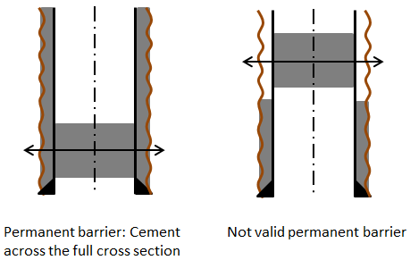
Permanent well barriers shall extend across the full cross section of the well, include all annuli and seal both vertically and horizontally. Hence, the plug or well barrier element set inside a casing, as part of a permanent well barrier, shall be located in a depth interval where there is a validated quality of the current cement / well barrier element in all annuli. An example of a valid and an invalid permanent well barrier is illustrated in the figure below.

It should be emphasised that the operator shall demonstrate that the cement and formation behind casing is qualified as a barrier at the time of abandonment. This means that the evaluation shall be based on the current state of the cement.
Furthermore, the well barriers shall be placed adjacent to an impermeable formation with sufficient formation integrity for the maximum anticipated pressure.
DWEA recommends that plugs should be set to:
- isolate any abnormally pressured formations
- isolate any hydrocarbon zones or water zones (this includes to isolate for potential crossflow from one formation to another.).
For quality assurance plugs in place shall be tested and verified. All cement plugs placed against formation shall be dressed off, load tested and pressure tested. Pressure test in open hole, where plug(s) is set between two formations is not required. For internal cement plugs, the first plug shall be verified by dressing off, load testing and pressure testing. The secondary plug shall be load tested or tagged. If there are doubts about the integrity of cement quality of the secondary plug, the plug must be dressed off.
Fluids in abandoned wells shall be suitable to minimise corrosion.
For exploration wells, planned not to be test produced or suspended, the drilling work programme shall include a detailed plan for plug and abandonment of the wells with the application for approval of the well operations. These wells shall be permanently abandoned when drilling operations as well as relevant logging and test programmes have been carried out and accepted by DEA and other relevant authorities.
DWEA considers the following standard and guideline regarding plug and abandonment are adequate to comply with Danish requirements.
- NORSOK-D010, Well Integrity Standard
- Oil and Gas UK, Guidelines for the suspension and abandonment of wells.
Other material than cement could be used as plugs in plug and abandonment operations.
However, the suitability of the selected plugging materials shall be verified and documented. Degradation of the casing over time should be considered.
The use of other material than cement for permanent well barriers shall be of equal or better quality and shall among other things have the following characteristics:
- provide long term integrity (eternal perspective)
- impermeable
- non-shrinking
- able to withstand mechanical loads/impact
- resistant to chemicals/ substances (H2S, CO2 and hydrocarbons)
- ensure bonding to steel
- not harmful to the steel tubulars integrity.
Wells will not be regarded as permanently plugged and abandoned until the sea floor is cleared and the well site is back to the original state. This includes the installation of an environmental plug, if required. Obtained documentation from sea floor clearance shall be submitted to DEA.
6.5. Well commissioning and well handover
This section covers the guidelines for tie-in the well to the production or injection facilities on the platform. It also includes the handover of the operational responsibility of the well to the operator’s production department.
The main goal of commissioning is to verify that the well can fulfil the overall requirements specified in the well design.
Commissioning should be a quality-focused process that besides the general verification of design specifications e.g., also should include accept criteria´s and/or performance indicators of safety critical elements as a way to measure the success of the commissioning and thereby positively contribute to a better and safer operation and performance of the well.
Well commissioning can be handled separately or can be incorporated during well construction.
Commissioning should be carried out similar or as close as possible to the wells operational conditions when connected to the installation for production or injection. All barriers shall be installed and tested before commissioning takes place.
Identified operational well conditions and risks shall be described and assessed according to the ALARP principle.
Well barriers and well barrier elements and their integrity shall be described and be a part of the well barrier schematic.
Well commissioning plan and results for all wells connected to the installation should be available offshore for the production team on the installation.
The commissioning should include a well handover documentation with specifications that clearly describes:
- well construction data and details
- x-mas tree schematic
- wellhead schematic
- casing and tubing schematic
- cement data
- perforated zones details
- barrier schematic illustrating all barriers and well integrity controls.
- pressure tests of
- wellhead
- x-mas tree
- fluid status for annuli and tubing
- well pressure status
- valve status.
It should also include
- the maximum allowable annulus surface pressures (MAASP) for each annulus including fluid type and weight in each annulus
- the maximum allowable operating pressures (MAOP) for each annulus.
information on electrical and hydraulic well control systems. Systems shall be tested and found fully operational
- other construction data are component details as manufacturer, component description, material, working pressures and temperatures, TAG-numbers and serial numbers
- anomalies for every component and any deviation that are identified shall be addressed and explicitly highlighted
- all relevant limitations for operating the well.
Safety and environmental critical elements (SECE).
6.6. Handover from production to well operations
This section covers the guidelines for hand-over from production to well operations prior to a well operation.
A handover documentation should as a minimum contain:
- the well schematic with status on all valves
- the latest SCSSV test and results
- annuli pressures
- flowing and shut-in tubing head pressures and temperatures
- any relevant production issues of the well such as scale, wax, asphaltene, hydrates, etc.
Copy of the safety and environmental critical element list from the SECE verification scheme
Well handover from production to well operations shall take place prior to any start of well operations.
7. Wells in the operational phase
7.1. Well operation
During the operational phase, all the wells must be controlled in such a manner that the following are adhered to at all times:
- safely operate the well within the well design operating envelope and according to any operating instructions.
- monitor wellbore integrity (see well integrity in section 9)
- monitor and maintain wellbore barriers
- monitor operating conditions for deviations from the well basis of design and potential risks to well integrity.
- identify and confirm wellbore problems affecting wellbore integrity.
- recommend the wellbore for repair as required.
7.2. Well operating envelope
The operator shall define the well operating envelope and operate within those criteria. If a well barrier element is degraded the maximum allowable annulus surface pressure, maximum allowable operating pressure, and the well operating envelope should be adjusted accordingly.
7.3. Well maintenance
The operator is responsible for the well maintenance during the entire life of the well. Well maintenance shall be part of the operator management system which includes:
- a method of identifying the maintenance routines for SECE; leading to a documented maintenance schedule and procedure
- a means of ensuring that the impairment of any SECE is identified
- a process for capturing any deferred maintenance
- provision for a register of overdue maintenance tasks and a process of analysis and control
- a process for remedying maintenance backlog items
- a mechanism to inform management about maintenance backlogs in general and specifically about SECE
- a documented maintenance history.
Operators are expected to identify any SECE that has degraded to the point where it does not meet its performance standard. In instances where SECE is found to be degraded, operators are expected to ensure that it is restored to its established performance standard and to notify the DWEA as outlined in appendix B2.
The maintenance schedule and procedure should include, but not be limited to:
- visual inspection and leak detection
- valves greased and function tested according to recognised norms and standards.
These elements include but not limited to:
- x-mas tree valves (closing function, closing times, and leakage rates)
- SCSSV (Surface Controlled Subsurface Safety Valve) (closing function and leakage rates)
- tubing (pressure test to a maximum containment pressure (shut in pressure))
- the well annuli (pressure build-up).
Well maintenance activities carried out should be fully documented on an ongoing basis. Function tests, test frequency and acceptance criteria shall at least follow recognised norms and standards.
When the well is handed over to operation, the well’s SECE are part of the verification scheme for SECE and not the well verification scheme.
8. Well testing
For exploration wells, the operator may consider for well test planning and operations to follow NORSOK D-007 Well testing systems, rev. 2.
Before test production, the test programme has to be submitted for approval as part of the well operation according to section 28 a.
Test production, perforating, hydraulic fracturing, acidizing or other chemical treatment of the well may only take place when special safety precautions, relevant for the operation, are observed. Test production using flare boom shall be started in daylight. Test production is not to take place when safety is adversely affected by weather and wind conditions. Caution shall be exercised to prevent accidental releases of chemicals and hydrocarbons to the environment.
Before start-up of test production, the drilling platform/drilling site (non-production installation) shall be specially prepared for the operation. All necessary fire precautions shall be taken. Valves, lines, temporary well test equipment and where relevant BOP shall be pressure and function tested.
9. Well integrity
9.1. Well control
The BOP and all pressure and well control equipment shall be designed, constructed, inspected, installed, maintained, monitored and tested in such a way, that it fulfils its intended purpose at all times and under all circumstances, and conform to recognised norms, standards and good industry practices. Furthermore, the BOP system and other pressure and well control equipment shall to the extent possible allow for remote operation.
Well control manuals, standards, procedures, measures and equipment must be established, implemented and maintained during the entire duration of all well operations related hereto in order to minimise the risk of loss of well control. In the event of any unintentional and unwanted influx of formation fluids into the wellbore, or any other uncontrolled event, implemented procedures and equipment must be sufficient to control and contain it, and prevent a blow-out.
A diverter system shall be installed and tested according to recognised norms and standards after the installation of the conductor casing.
In drilling operations, the BOP shall be installed as soon as practically possible, and no later than after the installation of the surface casing. The BOP system shall consist of at least one annular preventer, one set of pipe rams, either fixed or of variable type, blind rams or blind shear rams and choke and kill lines connected to the manifold. After the BOP installation and before drilling out from any casing string, all abovementioned BOP components and other pressure and well control equipment shall be function and pressure tested according to recognised norms and standards, such as API standard 53.
For well intervention operations, a BOP shall also be installed and configured for the well operation to be executed.
Function tests, pressure tests and test frequencies shall be according to recognised standards and norms such as the above-mentioned API standard.
9.2. Well barriers
During the entire life cycle of the well, two or more independent, verified and tested barriers shall be in place.
Standards and procedures covering testing, testing intervals, acceptance criteria, repair and restoration, replacement, determining position and status of the well barriers or any other well control measures shall be in place and implemented. Barrier tests should, if practically, be in the flow direction.
When the primary and secondary barriers fail, DWEA must be notified immediately. This requirement applies for the entire life cycle of the well, i.e. during well operations, the operational phase and well suspension.
In the event that one of the minimum two required barriers fails, the only allowed well operations would be those aiming at repairing and restoring or replacing it, except in the following case:
When one of the minimum two barriers fails during the operational phase (production or injection) and if the well has no ability to flow naturally, the well can - as an exception – be operated with only one well barrier provided the following has been fulfilled:
- A risk assessment has been performed and the residual risks are ALARP. The risk assessment has to include the potential risk of accidental releases from all zones of the well with a flow potential. Furthermore, an assessment of the potential failure of the remaining barrier has to be included
- A dispensation has been approved and granted according to the operator’s own management system
- The independent verification concludes that the potential risk of accidental releases of substances and materials are ALARP
- The well is monitored closely, and the abovementioned dispensation is controlled and regularly reviewed
- A plan to re-instate the minimum two barriers shall be in place. If the well is scheduled to undergo a workover, the plan shall be a part of the workover activities
- The DWEA shall be notified about the abovementioned
A well barrier can consist of one or several well barrier elements.
Well barrier elements contributing to maintaining well integrity includes, but not limited to:
- x-mas tree
- wellhead
- tubing hanger
- annulus safety valve
- surface controlled subsurface safety valve
- casing
- cement
- production tubing
- production packer
- completion string components (gas lift valves, chemical injection valves)
- mechanical plugs
- cement plugs.
NORSOK D-010 and Oil and Gas UK guidelines are considered as reference for well barriers and well barrier elements; those include well barrier design, construction, selection, maintenance, testing, verification and monitoring methods. Their recommendations are so far considered as good practice.
A well barrier schematic with all relevant data and test results should be devised for each well phase and well operation and should be updated to reflect the current state of the well.
9.3. Well integrity
Well integrity must at all times and under all circumstances be maintained during the entire life cycle of the well. All well components, barriers and elements contributing to maintaining well integrity shall be designed, constructed, inspected, installed, maintained, monitored and tested in such a way, that they fulfil their intended purpose at all times and under all circumstances, and conform to recognised norms, standards and good industry practices.
All these well components, barriers and elements critical (SECE) for maintaining well integrity shall be identified, and their position and complete status shall at all times and under all circumstances throughout the life cycle of the well be known. Procedures for monitoring, maintaining, testing, repair and restoration or replacement shall be in place and implemented. Criteria for failure and acceptance shall be specified, and immediate remedial action must be taken in case of failure or malfunction. Company standards and procedures should conform to recognised norms and standards such as NORSOK D-010 and Oil and Gas UK Well Life Cycle integrity guidelines and good industry practices in the North Sea region.
A well integrity categorisation system should be devised, and each well should be categorised based on its complete integrity status, where all well integrity components, barriers and elements are taken into account, and evaluated based on predefined criteria. All types of wells in operation, suspended or abandoned should be included in the well categorisation system. A procedure should be in place and implemented dealing with wells placed in the category representing wells with reduced well integrity.
A method of categorising well integrity is described in the Norwegian guideline “117 – Norwegian Oil and Gas Recommended guidelines for well integrity”.
The operator shall have a well integrity management system in place that shall cover the entire life cycle of the well and include all the wells. The operator shall extract the integrity status of all their wells from the well integrity management system and send it to DWEA. Guidelines on the content of such well integrity status are given in Appendix B2.
10. Chemicals, explosives, radioactive and waste materials
10.1. Chemicals and waste materials
The operator shall ensure that all chemical substances, including process fluids and diesel fuel, waste material, drilling fluid and drill cuttings generated at an installation, are stored and handled in a way that does not create a hazard to safety, health or the environment.
Chemical data sheet of all the substances used while operating shall be available on the offshore installation (rig if drilling from a rig, platform if intervention from the platform).
10.2. Explosive materials
Explosive charges for the perforating guns shall be stored in properly earthed metal containers. Explosives shall be stored in rooms specially approved for this purpose. Detonators, prima cord and perforation charges shall be stored separately.
Explosives shall be handled by specially trained personnel only.
10.3. Radioactive materials
All uses, including handling and storage of radioactive materials, require permission from the Danish Health Authority, Radiation Protection (Sundhedsstyrelsen, Strålebeskyttelse, SIS) and shall comply with their legislation.
SIS has regulations for the safe handling of radioactive materials including Normally Occurring Radioactive Materials (NORM) that can be present in scales formed in the well.
On the website of the Danish Health Authority, Radiation Protection, www.sst.dk/en/straalbeskyttelse/radioaktivitet, there are links to relevant legislation, and guidelines, contact information and forms for use when applying for permission for use of radioactive materials.
Regarding measuring instruments or other devices containing radioactive sources that constitute or over time can pose a safety, health or environmental risk, which is left in a well - after deciding that the source(s) cannot possibly be brought to the surface, since all practical possibilities have been explored, the operator shall notify DWEA, if possible, before making an amendment to the work programme.
The source shall be located, protected and isolated, so that it does not in any way come into contact with reservoir fluids. Source fixation and isolation can be performed using verified cement plugs of an appropriate length in accordance with good industry practices such as Oil and Gas UK guidelines for abandonment of wells, appendix E and NORSOK D-010 standard, Chapter 9 and table 15.24.
If further drilling activities are planned in the immediate vicinity of the isolated source, standards and procedures for anti-collision shall be implemented and identified risks shall be reduced as low as is reasonably practicable.
DWEA approval in connection with the above-mentioned amendment will typically be conditional upon the operator has received approval by SIS for the radioactive source(s) to be left in the subsoil.
11. Safety incidents and near misses
Safety incidents and near misses shall be notified and reported to DWEA according to executive order on registration and notification of accidents etc. in connection with offshore oil and gas operations etc. and “At-vejledning om registrering og anmeldelser af ulykker, m.v.” for guidance on reporting, registration and investigation of incidents and near misses, etc.
This is part of the EU implementing regulation No. 1112/2014 on offshore safety, which includes data and information on well control requiring actuation of well control equipment, or failure of a well barrier requiring its replacement or repair.
12. Documentation to DWEA
Approval documentation (section 28a)
- drilling programme
- completion programme
- workover programme
- plug and abandonment programme
- report from the well verifier and the operator measures based on this report
- amendments to programme.
Notification documentation (section 28b)
- a monthly update of planned well operations for the next quarter with a short and sufficient description of the operations to be carried out including
- a list of well operations carried out during last period
- work programme or
- a description with objectives of the well operations to be performed.
Daily well operations documentation
- daily drilling reports (DDR)
- daily geology reports (DGR).
Other documents may include
- drilling schedule (frequency to be agreed upon with DWEA)
- well integrity status (frequency to be agreed upon with DWEA)
- end of well report, not later than 6 months after end of operations
incidents and near misses related to wells.
Daily Drilling Reports (DDR)
The operator shall ensure that a daily report of the latest 24 hours of operation is sent to the authorities before 11.00 am by email (owa@at.dk). The reporting commences from the time of a drilling rig or the well operation equipment is rigged up for operation. The reports should cover operation up to 6.00 am on the reporting day.
The report shall include the information as per appendix B1.